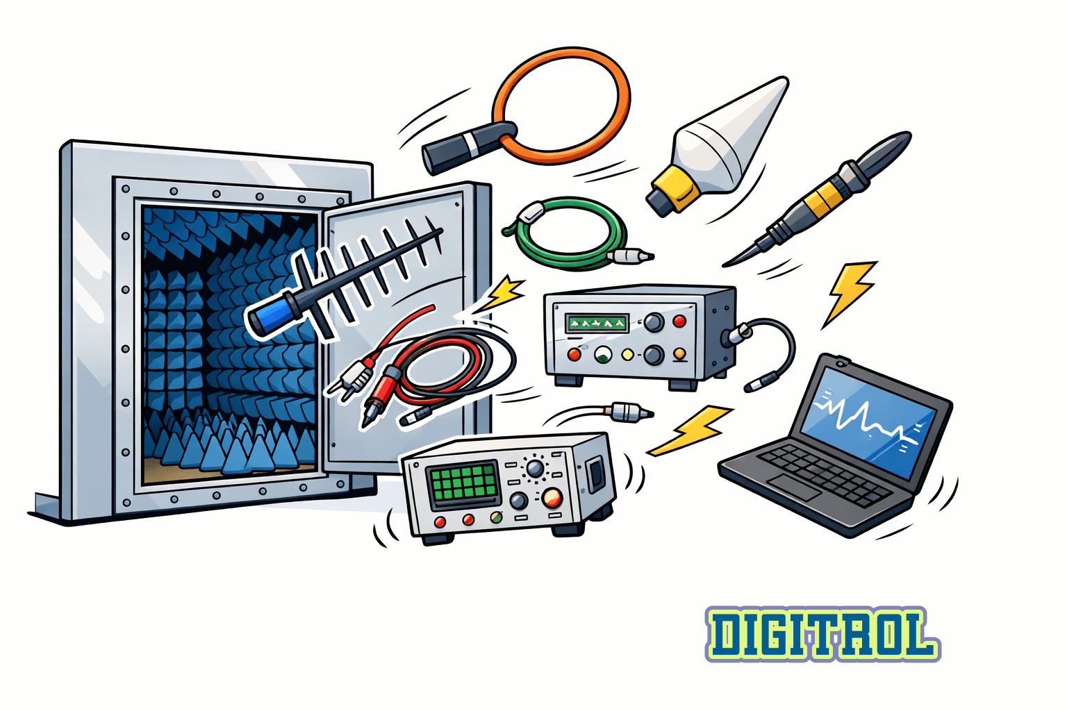
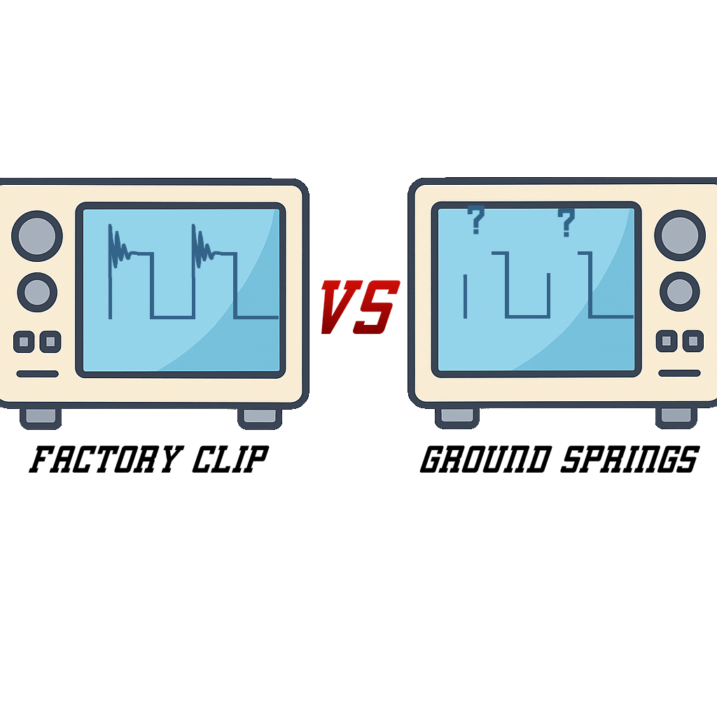
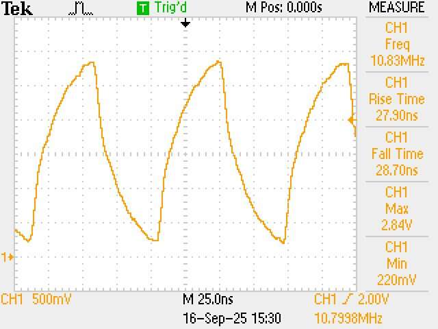
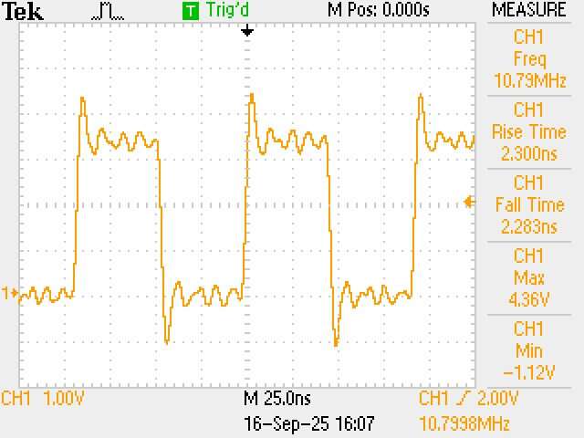
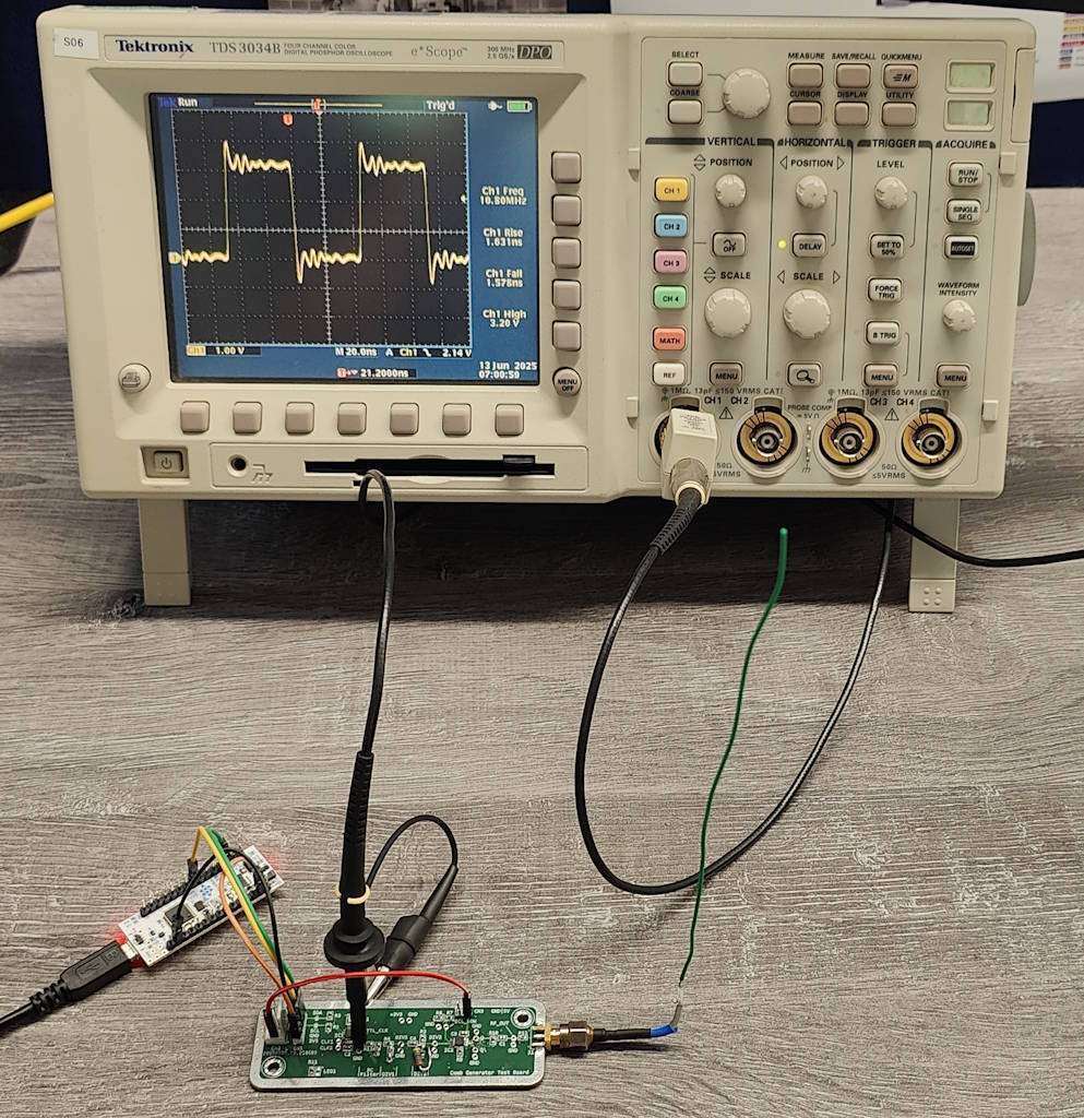
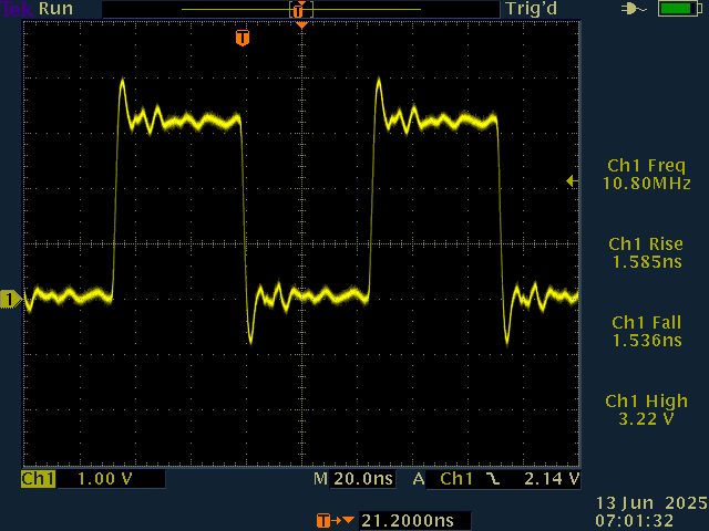
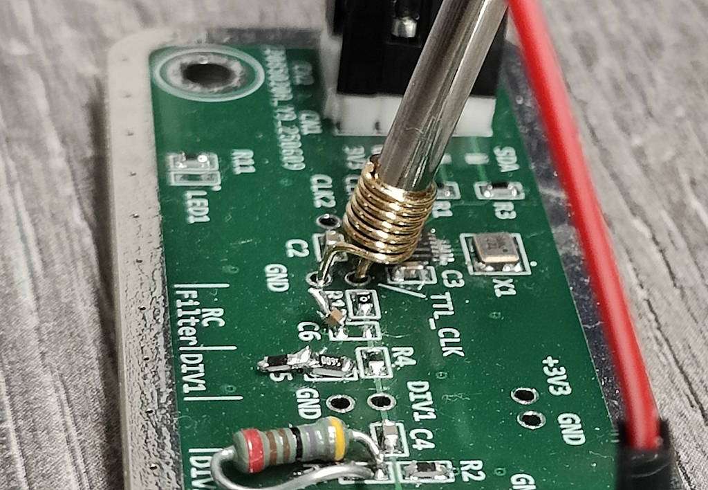
Oscilloscopes – Grounded Methods

Your Oscilloscope Is Only As Good As The Way You Connect It!

One element that has caught many engineers off guard is ground loop inductance. The standard long ground clip that comes with many oscilloscopes may not be cutting it when you are dealing with digital signals with fast edges and high frequencies. The LC circuit that is introduced can cause extra ringing and overshoot that will be introducing errors to your readings. 

To showcase the effects of this, we decided to do a practical demonstration, The test we carried out used the standard ground lead and then we used a much shorter spring tip that provides a much shorter ground.

Test Setup

  • Tektronix TDS2012B 100MHz Oscilloscope
  • Tektronix P2220 Probe
  • Comb Generator Test Board (with Si5351)

To start, we powered up our comb generator test board (which has an Si5351 clock generator set to output a 10MHz square wave clock), and connected it to our Tektronix 100MHz oscilloscope.

oscilloscope connected to small circuit board
Triangle wave plot from oscilloscope

This is not the square wave we expected to see. The probe was set to 1x attenuation and produced a a sawtooth pattern. If you were to look at this as it was, you could assume that the clock generator circuit was faulty. At 1x attenuation, the probe has a capacitance of 95pF and a bandwidth of 6MHz, so this pattern would be expected at higher frequencies. 

Setting the probe to 10x attenuation allowed us to see more clearly what was going on. At 10x attenuation, the capacitance is 16pF and the bandwidth rises to 200Mhz. Now we can almost see the square wave we are expecting, but not quite.  

square wave trace on oscilloscope with significant ringing

This is the critical point where we must ask ourselves: do we trust our measurement? An oscilloscope will always have an effect on the source signal, and will never perfectly reproduce the signal of interest. To increase the usefulness of our measurement, we must upgrade our technique.

oscilloscope connected to small circuit board

At this point we went back to the cupboard and brought out the higher spec’d scope:

  • Tektronix TDS3034B 300MHz oscilloscope
  • Tektronix P6139A Probe
oscilloscope trace showing ringing

This was important to make sure that it was indeed an error caused by something other than the measurement apparatus. And we saw exactly what we were expecting. The same square wave with the ringing on the rising edge. 

The Less Than Complicated Solution

As we can see, keeping the probes the same yielded the same result on 2 different oscilloscopes. The common denominator being the probes themselves. 

The sinusoidal waves seen on the rising edge of the square waves are caused by inductance introduced by the length of the probes grounding lead. At 120mm long, this may not appear to be significant, but will be introducing an inductance of approximately 200nH.

Reducing the ground lead was an easy solution. By using some ground springs that can be found online, you can significantly reduce the effects of this impedance.

photo of oscilloscope probe with short ground clip
oscilloscope trace showing square wave with almost no ringing

And here we have the final result. A much improved trace at high frequencies. Still not perfect, but a much better reading than when we started.

See all our news